System Controller – LAS-F
System Controller
FOLLOWING STEP BY STEP FOR SPECIFIC PRACTICE. YOU WILL KNOW THE DETAIL OPTIONS THROUGH THE PRACTICES.
01 OVERVIEW >02 KEY USP > 03 PREINSTALLATION > 04 CABINET INSTALLATION > 05 CABLING > 06 LDM ATTACHMENT > 07 SYSTEM CONTROLLER > 08 EVALUATION > 09 CERTIFIED PARTNER
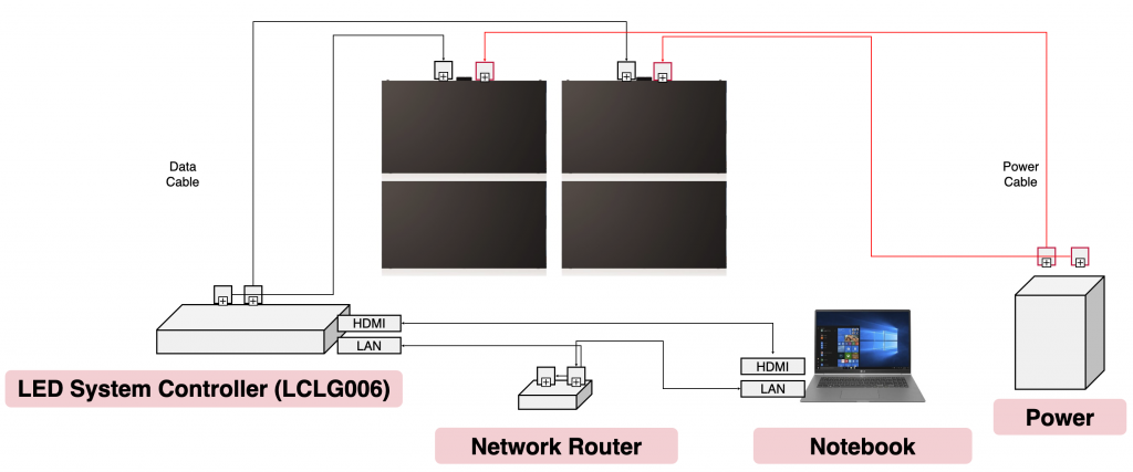
Basic system connection
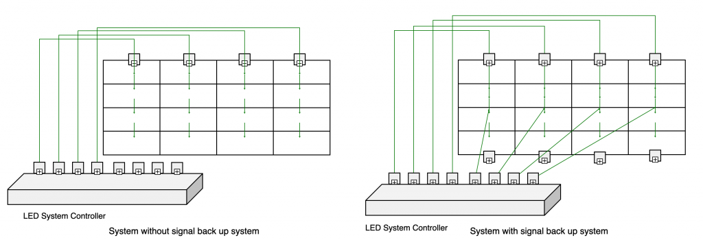
LED screen redundant configuration with two LED System controller (LCLG006)
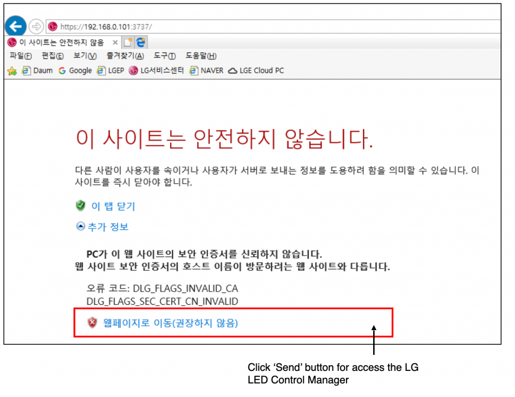
(0) LG LED Control Manager Setup
- Access https://192.168.0.101:3737 to setup the LG LED Control Manager of LCLG006
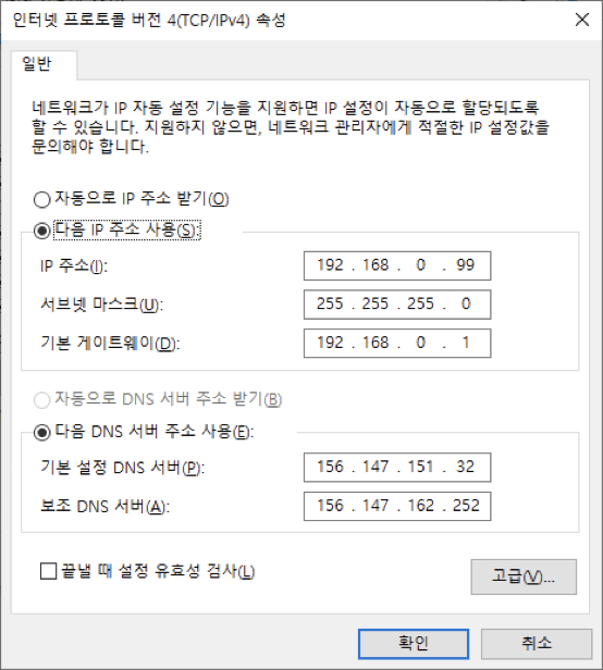
- Assign a fixed IP address to the LED System Controller and PC which installed LED Assistant S/W.
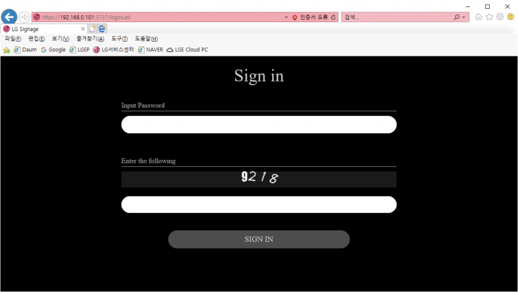
(1) Log in
- Input Password and 4 digit code. (The default password is ‘Serial No’+’LGe12#’.)
(2) Connecting to the LED controller
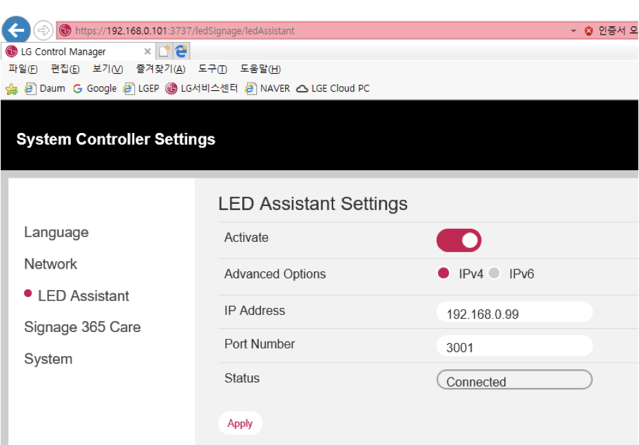
- Enter the IP Address of the PC where LED Assistant is installed and Click the ‘Apply’ button
- The Status will be changed from ‘Not Connected’ to ‘Connected’.
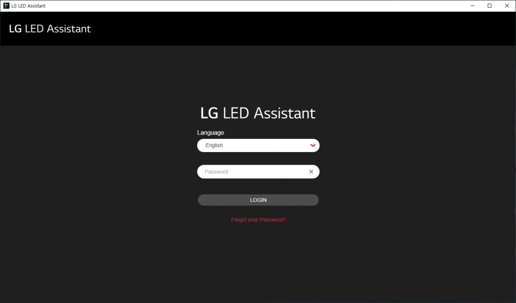
(3) Running LED Assistant software
- Click the LG LED Assistant icon in LG LED Assistant Installation folder or Start > All Programs > LG LED Assistant. Or enter https://Server IP Address:8787 in the Chrome browser.
- LG LED Assistant is enabled, Input password and Click ‘LOGIN’ button. (The default password is ‘000000’).
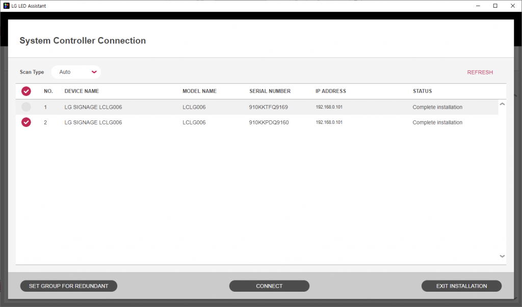
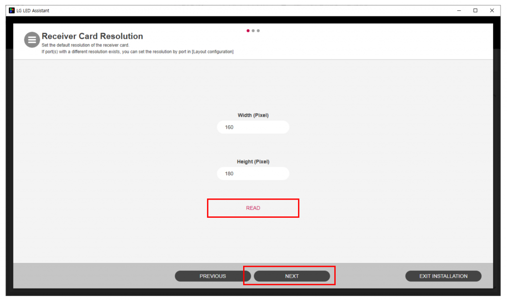
(4) Configuring the LED controller
- Select LED System Controller at connection dialog and Click ‘Connect’ button.
- READ the Receiving Card Resolution and Click the ‘Next’ button.
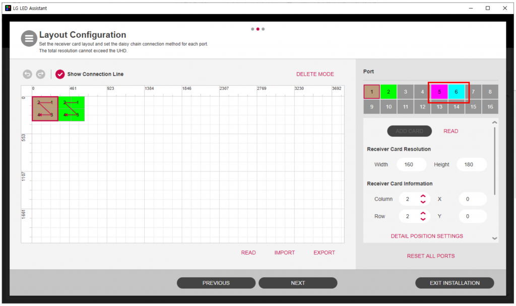
- Click the Port Number and ‘ADD CARD’ button.
- Colored Port Number is shown with LAS unit case
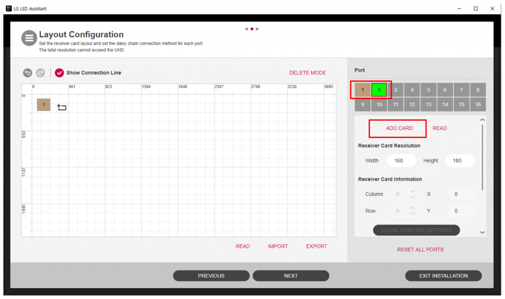
- Update the Receiver Card Information and Starting Point of each block.
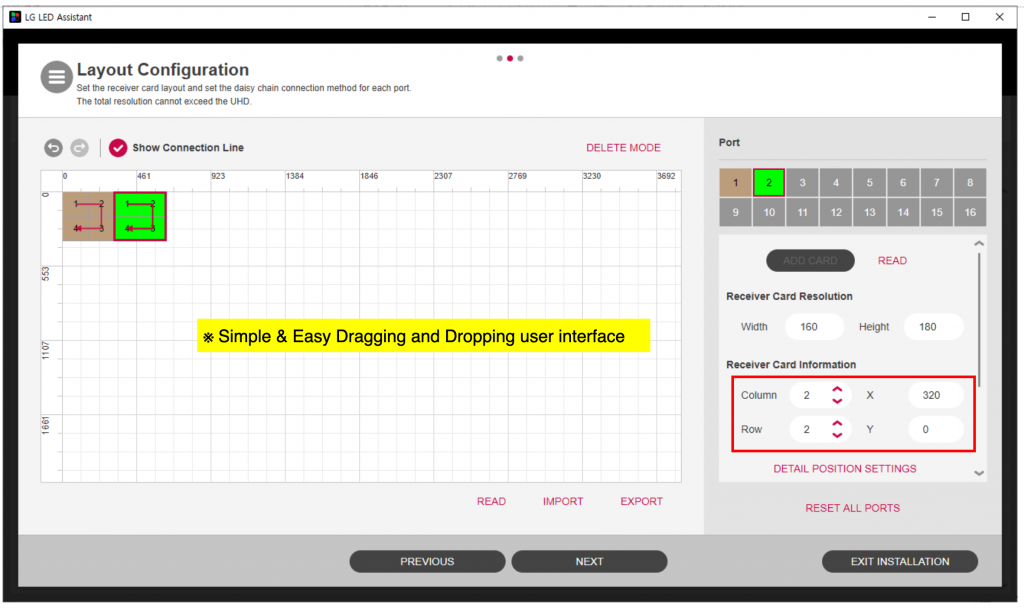
- Delete the Receiver Card Mapping Information by clicking the right button of mouse.
- Draw the New Receiving Card Mapping Information by clicking the left button of mouse. Finally Click ‘NEXT’.
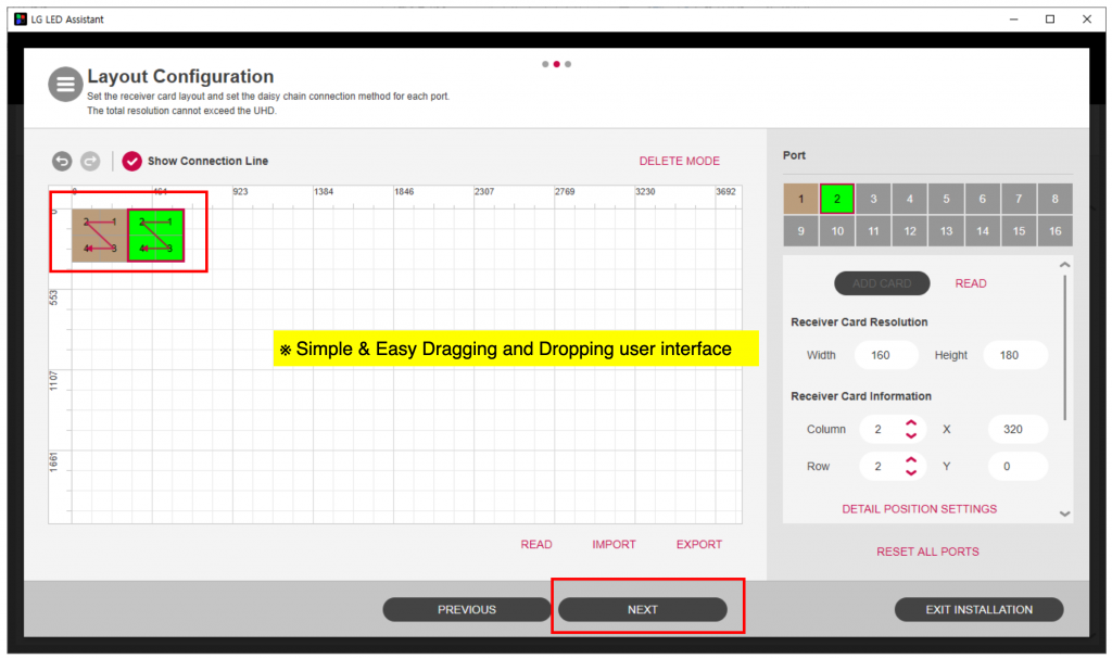
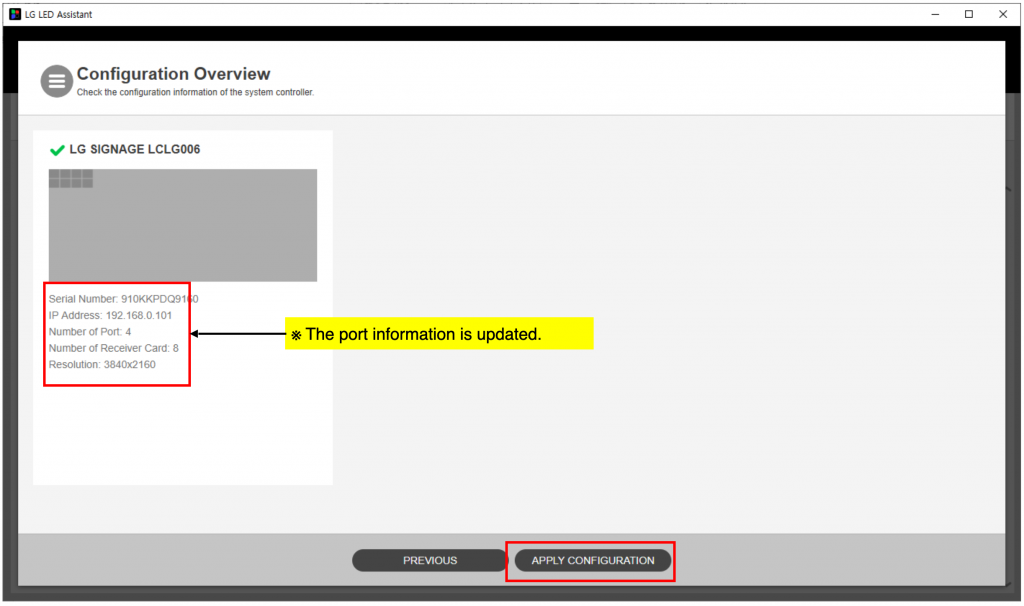
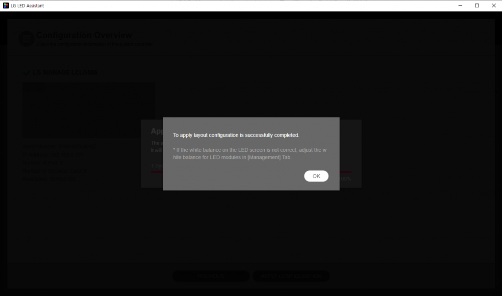
- Click on ‘APPLY CONFIGURATION’.
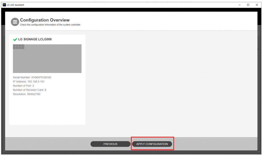
- The LED screen configuration is done.
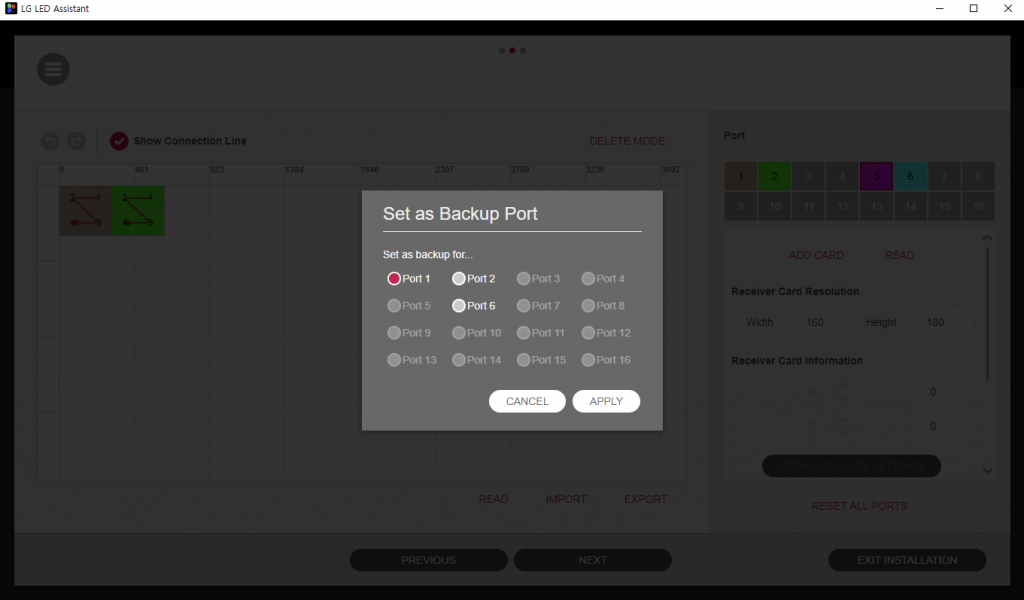
(5) Port Redundancy configuration
- To secure the system stability, LED system controller provides signal backup solution in order to prevent LED screen failure using unused port.
- Check the activation of redundancy port number at Layout Configuration.
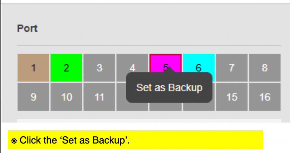
- Set the right Port number as Backup Port and Click ‘APPLY’.
- Set the left Port as Backup Port and Click ‘NEXT’.
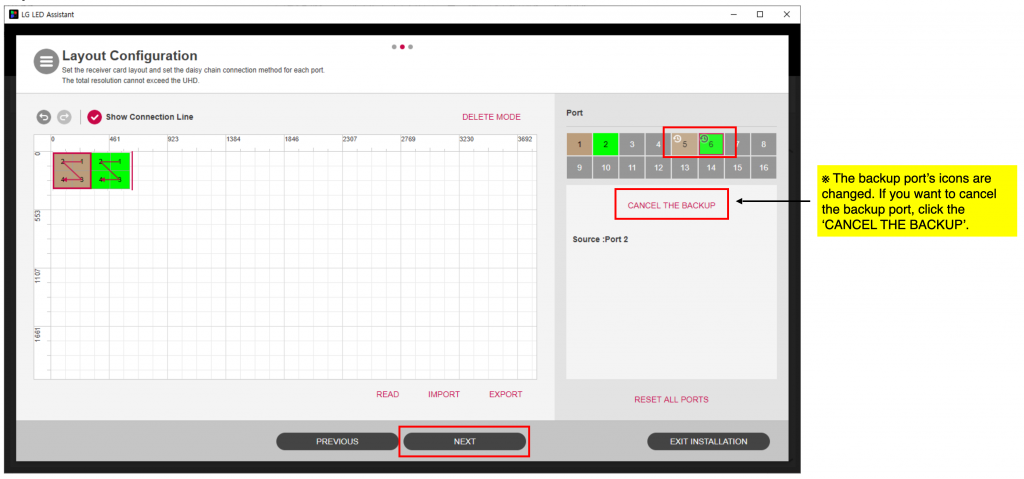
- Click on ‘APPLY CONFIGURATION’.