System Controller – GSCD
System Controller
FOLLOWING STEP BY STEP FOR SPECIFIC PRACTICE. YOU WILL KNOW THE DETAIL OPTIONS THROUGH THE PRACTICES.
01 OVERVIEW >02 KEY USP > 03 PREINSTALLATION > 04 CABINET INSTALLATION > 05 CABLING > 06 SYSTEM CONTROLLER > 07 EVALUATION > 08 CERTIFIED PARTNER
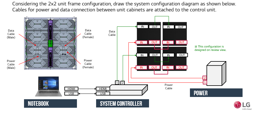
Basic system connection
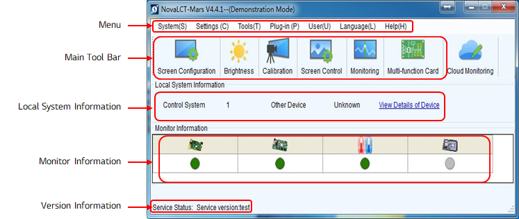
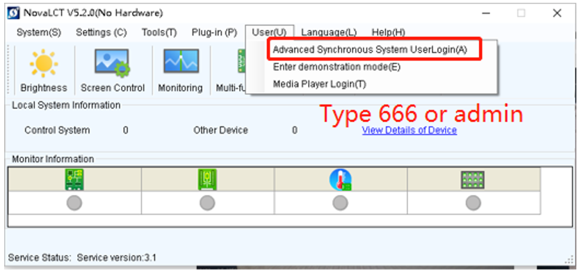
(0) Start UP screen
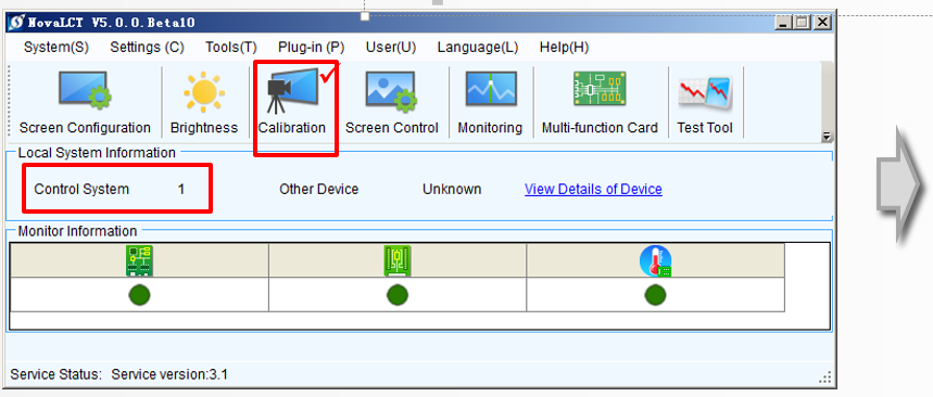
•After the software is enabled, there comes the software interface as in the following picture.
Please ensure you are using the latest supported version.
(1) Log in
•After the software is enabled, there comes the software interface as in the following picture.
Please ensure you are using the latest supported version.
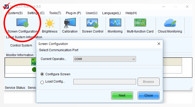
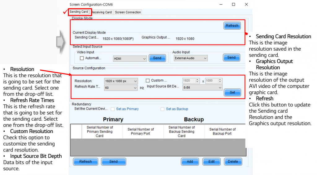
(2) Sending Card Setting
The hot backup setting makes the connection of relating the sending cards into a loop. In the case that some Ethernet cable within the loop is disconnected by accident, a slave device will take over the sending cards behind the disconnection point and keep the LED display working normally.
- Set the Current Device : Set the current device as the primary or backup device.
- Master Device
- − Master Sending Board Index: this is the index of the sending card which is to be set as a master device.
- − Master Port Index: this is the index of the Ethernet port of a master device (sending card) that is used to output data.
- Slave Device
- −Slave Sending Board Index: this is the index of the sending card which is to be set as a slave device.
- −Slave Port Index: this is the index of the Ethernet port of a slave device (sending card) that is used to output data.
- Refresh : To update the current hot backup information.
- Send : To send the hot backup settings to hardware.
- Add : To add a new record into the hot backup info list.
- Edit : To edit a record in the hot backup info list.
- Delete : To delete a record in the hot backup info list.
(3) Receiving Card Setting
I recommend you only use ‘Read from receiving card’ when you correct a cabinet resolution information.
If you write the wrong parameters to memory, the screen will malfunction.
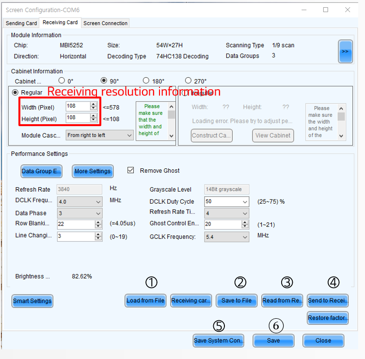
- Load File : load a receiver card file to software, file format is “.rcfgx”
- Save File : save a receiver card configuration as a file.
- Read from Receiving card : read configuration from receiver card
- Send to Receiving card : send configuration to receiver card
- Save : save configuration to receiver card permanently.
- Save System Configuration File : save complete configuration including sender card, receiver card and screen as a file, file format is “.scfg”
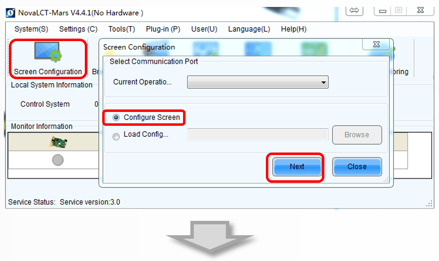
(4) Screen Connection Setting
- Press ‘Screen Configuration’ Icon,
- select ‘Configure Screen’ then press ‘Next’.
- Enter ‘Screen Connection’ page,
- select ‘Screen number’ as ‘1’ then press ‘Config’.
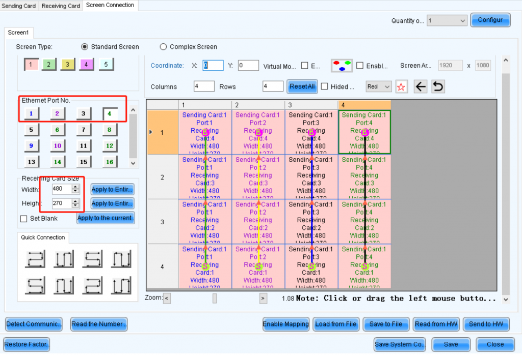
- Select ‘Standard Screen’,
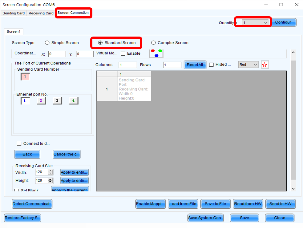
- set how many Scan Boards (Receiver cards) are used in Column and Row,
- set how many pixels one Scan Board (Receiver cards) manages in Width and Height
- connect Scan Boards (Receiver cards) based on fact (Viewing from the front of LED screen).
- Correct the Scan Board Size
- Select the scan board need to be corrected,
- change the width or height value then click the scan board area.
- follow this step to change other scan board size.
- Click ‘Send To HW’, a window will appear at few seconds later and click’OK’ to continue. At Last, click ‘Save’ to save the setting then click ‘OK’ to finish
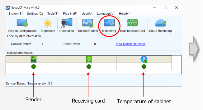
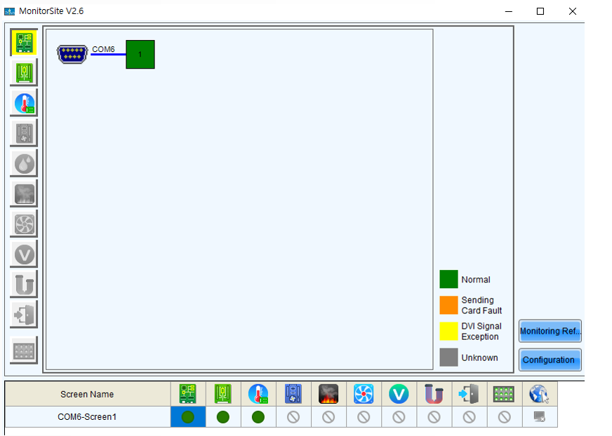
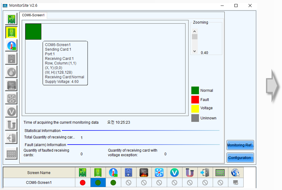
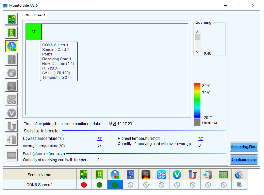
(5) Monitoring
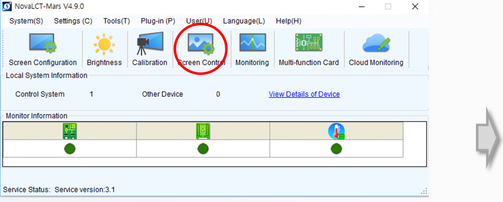
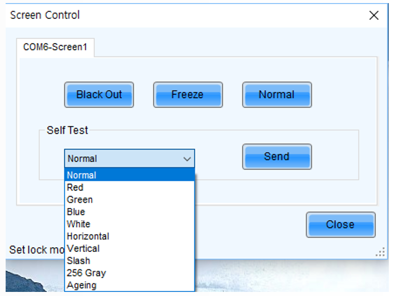
(6)Screen Control
- Black Out : Show nothing on the LED display.
- Freeze : Always show the current image frame of the LED display.
- Normal : Switch the LED display back to normal from Black Out or Freeze.
- Self Test : Show the test images generated by the receiving card for LED displays aging test or error detecting.
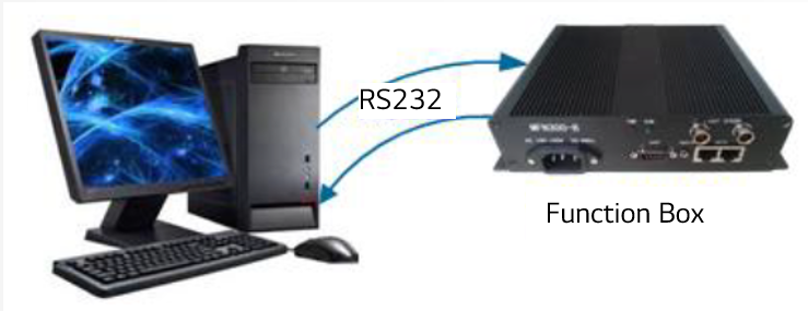
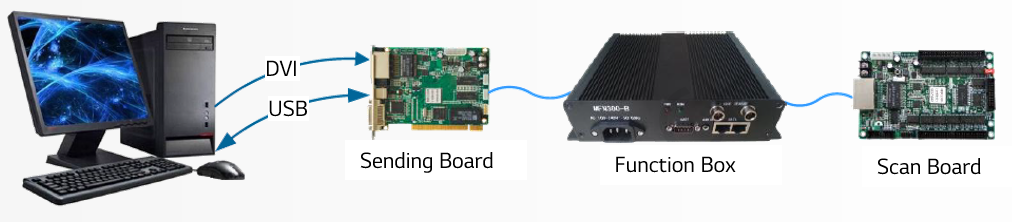
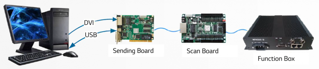
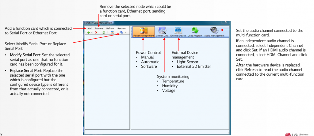
(7)Function Box Connection
Ⓐ Connect function box to computer directly by RS232 serial cable.
Ⓑ Connect function box between sending card (or independent controller) and the first receiving card.
Ⓒ Connect function box to the last receiving card.
(8)Function Box Setting
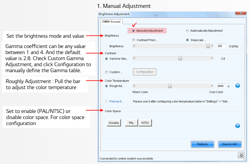
(9)Brightness Setting
1. Manual Adjustment
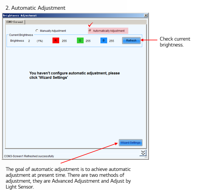
2. Automatic Adjustment
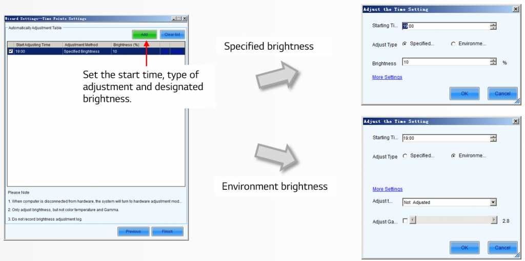
You can configure multiple time points,
(Automatically Adjustment > Advanced Adjustment)
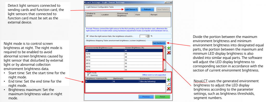
- Specified brightness: The brightness of LED display from certain time on designated by the user, the brightness is fixed.
- Environment brightness: The brightness of environment from certain time on designated by the user, the software will automatically adjust the LED display brightness in accordance with the parameters set by the users as well as environment brightness information collected by light sensors so that the LED display can exhibit proper brightness under different environment brightness.
Configure light sensors (Automatically Adjustment > Advanced Adjustment > Environment brightness)
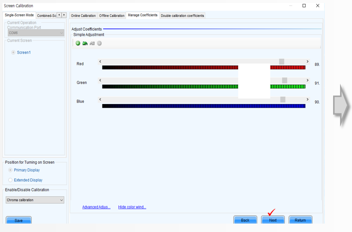
(10)Writing Calibration Data
The below table shows whether cabinets have a memory for calibration data on modules or not.
If a cabinet doesn’t have the memory on modules, you have to save calibration data to the receiving card.
using provided SW(NovaLCT-Mars) after replacing module or receiving card.
Please follow the instruction at next page if your cabinet doesn’t have the memory on modules.
| 1 | L(FISS) | LBE067/080/100/133/160DD4 | X |
| 2 | B | LBH062/078/100/106/133/160/200DD4-B | X |
| 3 | ER | LBE039/046/059/069/078/104DD4 | O |
| 4 | GM | LBE060/080/106/120/160DD1-M | O |
| 5 | QE | LBE046DD4-Q | O |
| 6 | C | LBM090/144DD4 | X |
| 7 | M | LBM100/160DD4 | X |
| 8 | E | LBM312DD4 | X |
| 9 | SL | LBM089/100DD4 | O |
| 10 | L(SS) | LBB100/133DD3D | X |
| 11 | HD | LAE012/15DD6 | O |
| 12 | S | LAE018/24/29/36DD6 | O |
| 13 | ER | LAE029DD4DE/LAE039/48DD4D | O |
| 14 | X | LAC025/29/39DD4 | O |
| 15 | SF | LAX025/40DD4 | X |
Save calibration data to the spare when a module is replaced
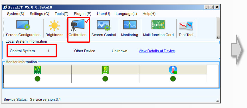
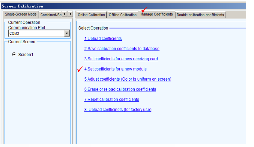
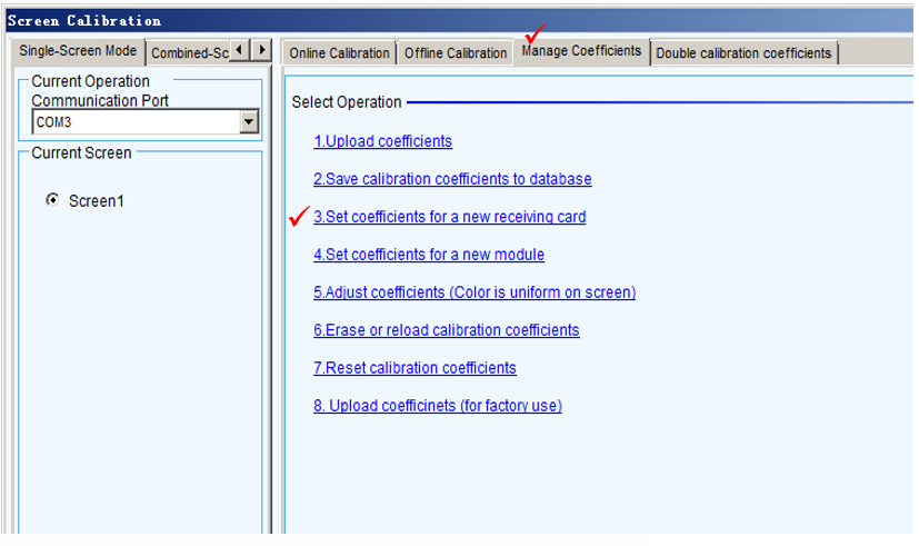
Open the NovaLCT-Mars, check the control system has been connected. Click option ‘calibration’. •Click option ‘manage coefficients’. •Click option ‘4. set coefficients for a new module’.
Save calibration data to the spare when a module is replaced
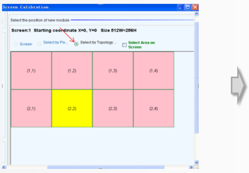
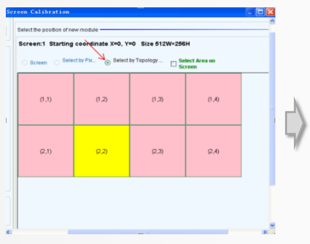
Click option ‘select by topology or list’, then pitch on the corresponding cabinet which you want to send calibration data to (Front view of the LED display). When the area color turns to yellow, double click. •At the module size option , write the module resolution.
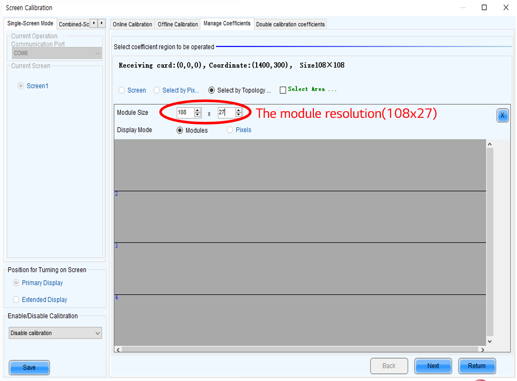
Save calibration data to the spare when a module is replaced
Select the module which has just been replaced. •When the area color turns yellow, click the option “next”
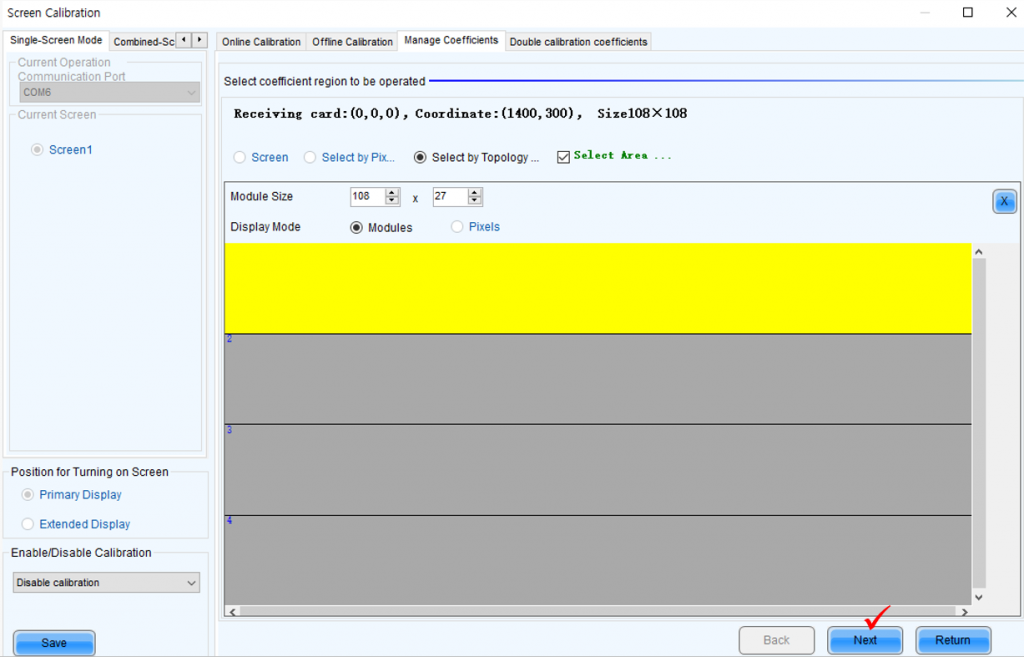
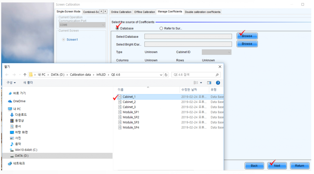
When a module’s replaced, How To Save Calibration Data To The Spare
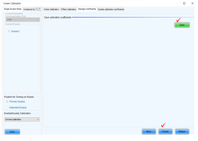
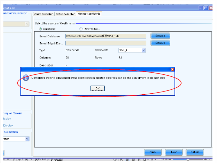
Click database, click options ‘browse’ to chose the spare module ID. Every spare module has it’s own ID. In general case, we can see it in the back of the module. •Click the option ‘stable uploading’, the click the option ‘next’.
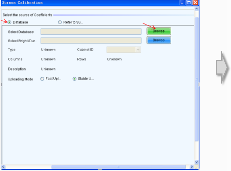
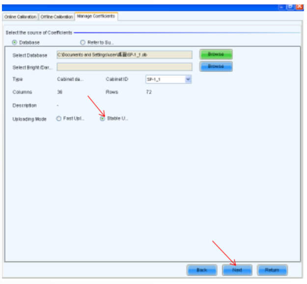
When a module’s replaced, How To Save Calibration Data To The Spare
After that, wait until the system it’s ok.
When a receiving card’s replaced, How To Save Calibration Data To The Spare
Click option ‘calibration’ •Click option ‘3. Set coefficients for a new receiving card’. •
When a receiving card’s replaced, How To Save Calibration Data To The Spare
Select file which is provided and press the next button. •
When a receiving card’s replaced, How To Save Calibration Data To The Spare •