LDM Attachment – LAS-F
LDM Attachment
FOLLOWING STEP BY STEP FOR SPECIFIC PRACTICE. YOU WILL KNOW THE DETAIL OPTIONS THROUGH THE PRACTICES.
01 OVERVIEW >02 KEY USP > 03 PREINSTALLATION > 04 CABINET INSTALLATION > 05 CABLING > 06 LDM ATTACHMENT > 07 SYSTEM CONTROLLER > 08 EVALUATION > 09 CERTIFIED PARTNER
LDM Attachment
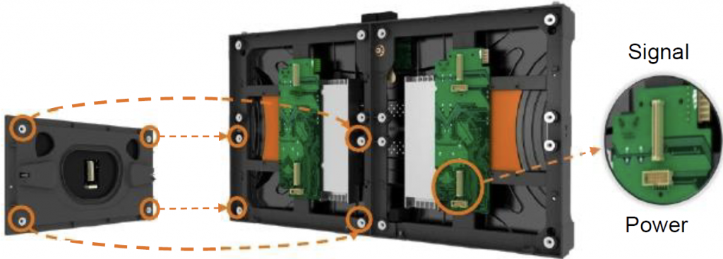
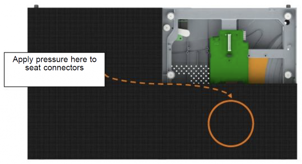
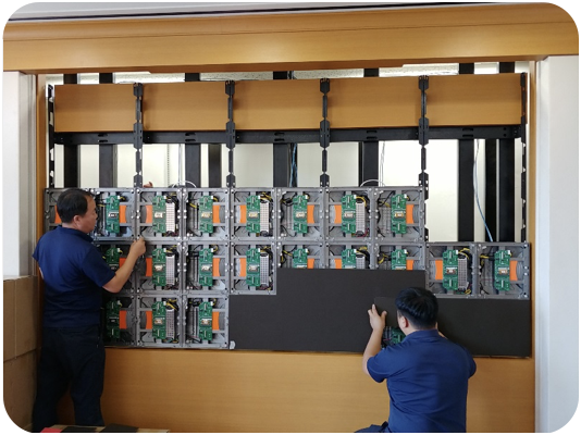
- Avoid any impact on the edges when installing the module
- Do not shake the module while aligning the connectors
- The power connector has 12 pins and is easily bent during connection, please be very careful while performing the connections.
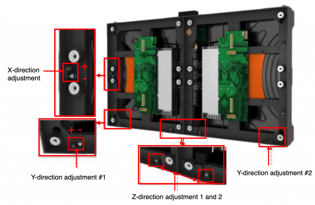
6-way adjustment mechanism
- 6-way adjusting mechanism needs a 4mm Allen key
- X-direction adjusting range : 5mm
- Y-direction adjusting range : 5mm
- Z-direction adjusting range:0.8mm
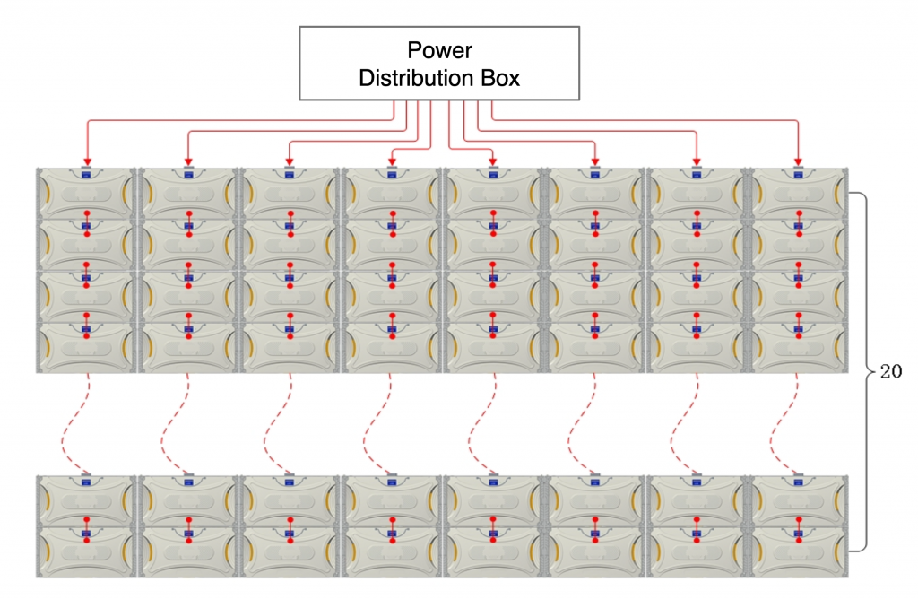
6-Power cable wiring
- AC power supply transmits downwards from the top of each row in a daisy chain.
- When the AC 220V is applied to the screen as shown to the right, the maximum Cabinet number which can be connected with 1 AC 220V source is 16.
Data Connection
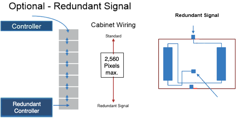
- When routing cables for the LAS Series LED display cabinets, check your system diagram first. If the total supported resolution is exceeded, additional RJ45 cables will need to be routed to the correct location in the column to support the secondary signal.
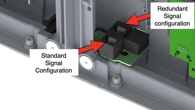
- Each cabinet has a second RJ45 connection point that provides a point to introduce a new signal to the LED screen. To use this, a manual reconfiguration of the internal cabinet wiring is necessary. Schematically, the RJ45 input cable (1) will be swapped to bring the signal in from the rear connecter as shown in Picture 3.2.
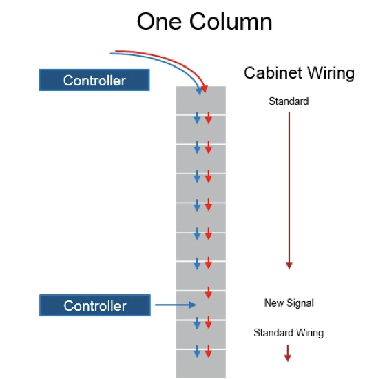
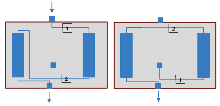
- To transfer the signal, unplug the cable currently plugged into the bottom of the right hand signal board. Then remove the input cable from the top of the cabinet, and plug the input cable into the rear signal port and the right side control board’s bottom port.
- Next, take the cable you unplugged and route it to the top of the right hand signal board.
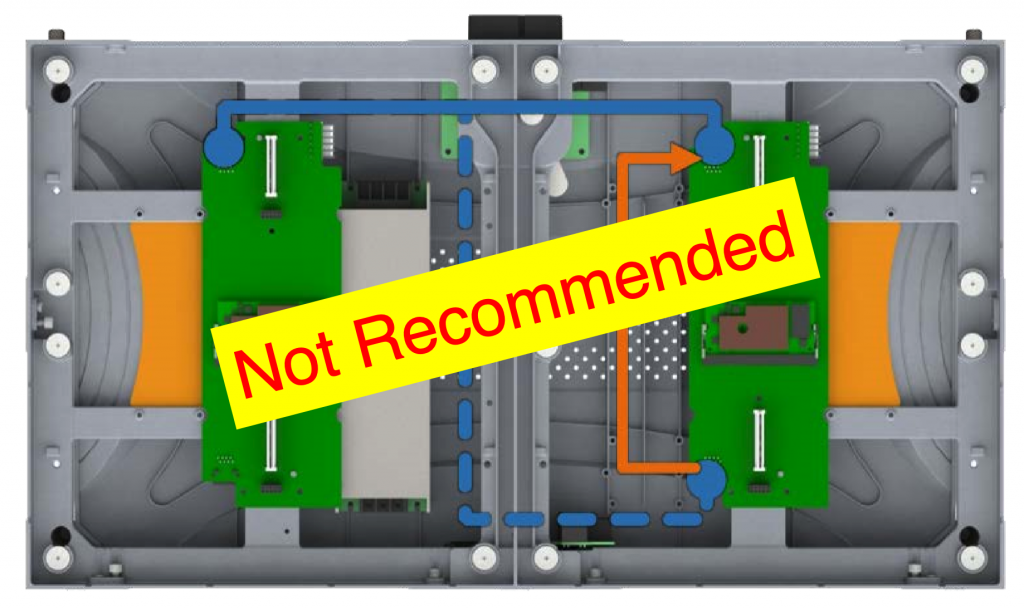
- Cabinets may be configured to support redundant signal input as shown below.
- For redundant signal applications, the additional signal will be introduced at the bottom of the column. That unit will require internal rewiring to set it up to pass the signal from the rear port up through the column. Remove the pass-through RJ45 from the standard signal configuration and plug it into the connector toward the back of the chassis. This will bring the video signal in from the port on the back of the cabinet. To access the port, remove the perforated port cover sticker.