Cabling – GSCA
Cabling
FOLLOWING STEP BY STEP FOR SPECIFIC PRACTICE. YOU WILL KNOW THE DETAIL OPTIONS THROUGH THE PRACTICES.
01 OVERVIEW >02 KEY USP > 03 PREINSTALLATION > 04 CABINET INSTALLATION > 05 CABLING > 06 LDM ATTACHMENT > 07 SYSTEM CONTROLLER > 08 EVALUATION > 09 CERTIFIED PARTNER
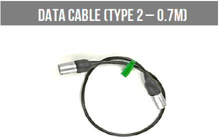
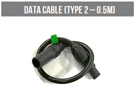
Data Connection
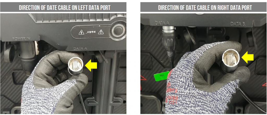
The connectors should be pushed firmly home when plugging in the data jumpers.
The connections are fully sealed when the black rubber nub clicks back out and locks the connector in place.
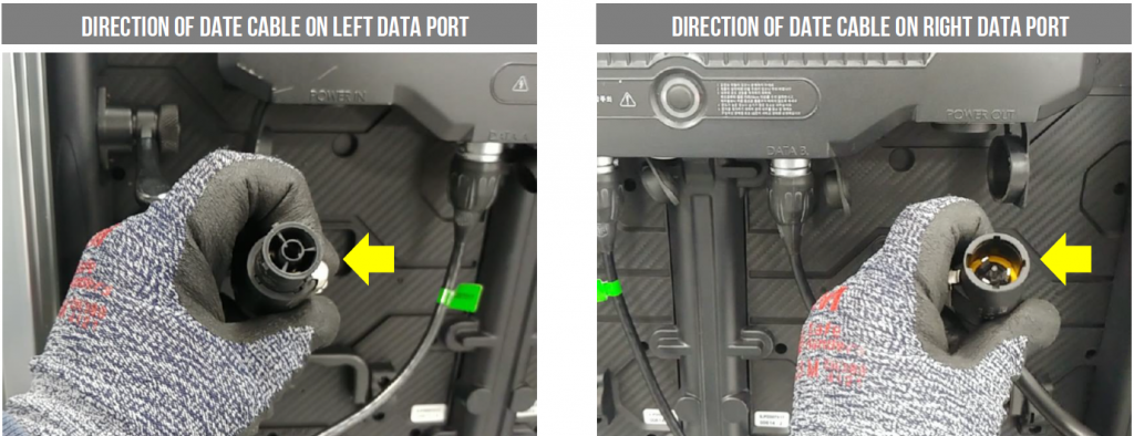
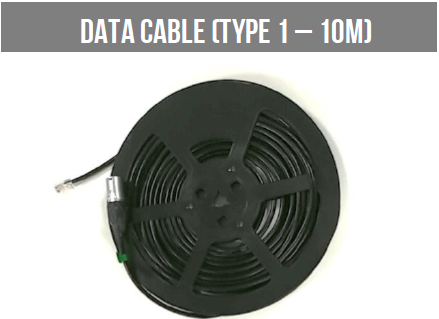
The short data cables in the box are used to interlink the panels
The short data cables in the box are used to interlink the panels
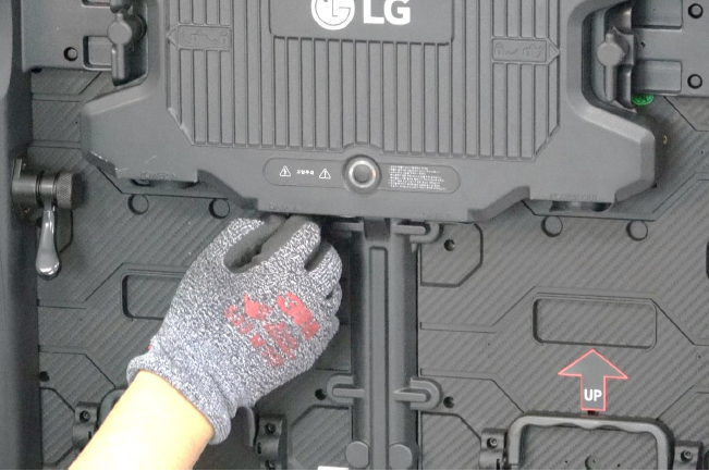
Take off cover cap of data port
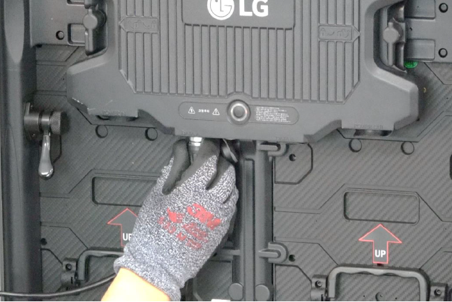
Insert data cable to data port

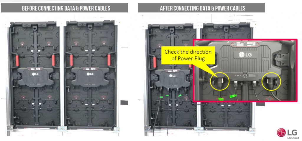
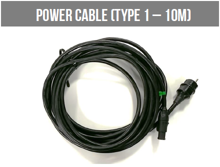
Power Connection
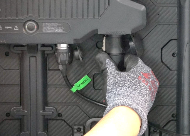
The Power output port: Neutrik power socket(GSCA Generation 2)
Insert the power cable at an angle of about 15 degrees.
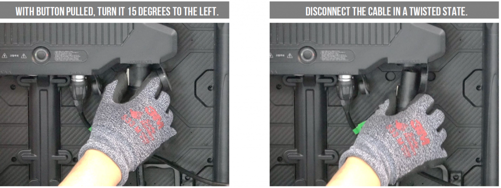
Turn it in the right direction until it sound ‘tick’. Disconnect the cable in a twisted state.
Take off cover cap of Power port
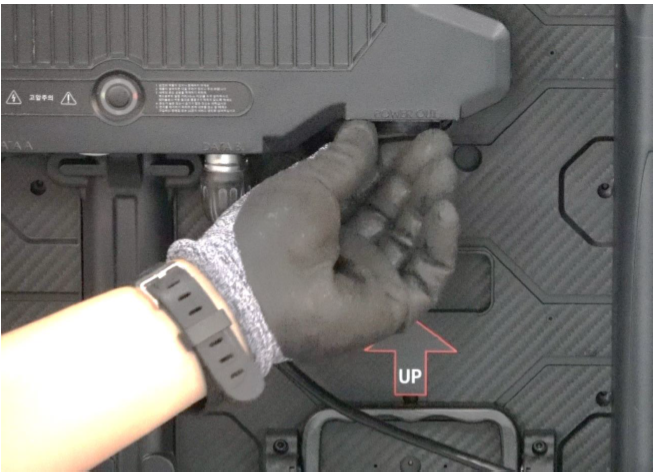
Insert power cable to power port
Cabling Variation
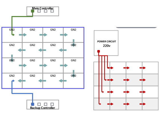
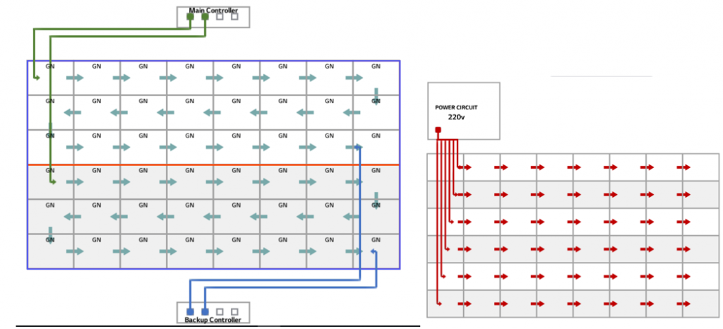
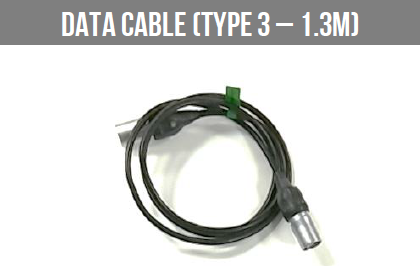
Main Data Cable from Source
Main Power Cable from System Controller
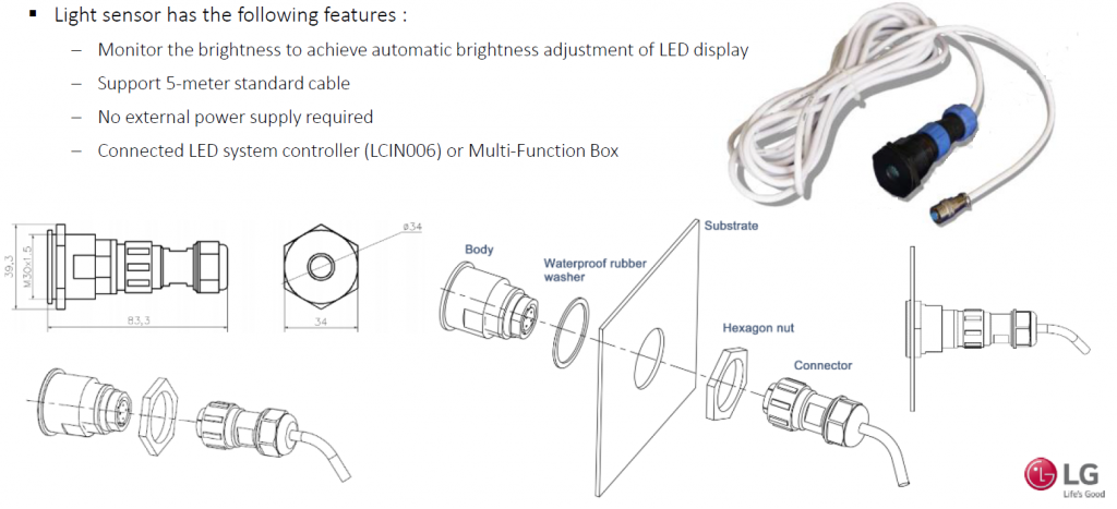
Light Sensor – GSCA