Installation – BLOC
Installation
FOLLOWING STEP BY STEP FOR SPECIFIC PRACTICE. YOU WILL KNOW THE DETAIL OPTIONS THROUGH THE PRACTICES.
01 KEY USP > 02 COMPONENT > 03 CONFIGURATION > 04 INSTALLATION > 05 SOFTWARE CONFIGURATION > 06 EVALUATION > 07 CERTIFIED PARTNER
Installing Wall Mount Bracket
1. Marking the location of the wall mount bracket
Refer to the installation dimensions below and mark the location of the Wall Mount Bracket on the wall using a 3D Red Beam Self-Leveling Laser.
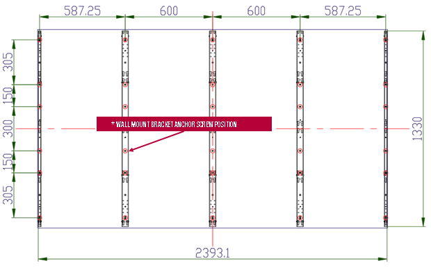
It is recommended to use a two-axis laser level to mark all of these screw fixing points on the wall.
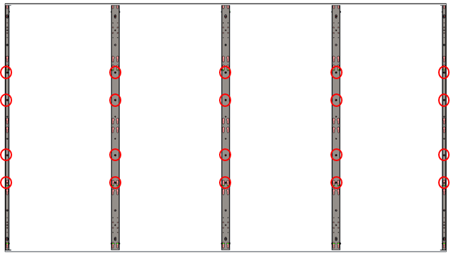
2. Example of marking the screw fixing point
An example of marking the screw fixing point to install the Wall Mount Bracket on the wall is shown in the figure below.
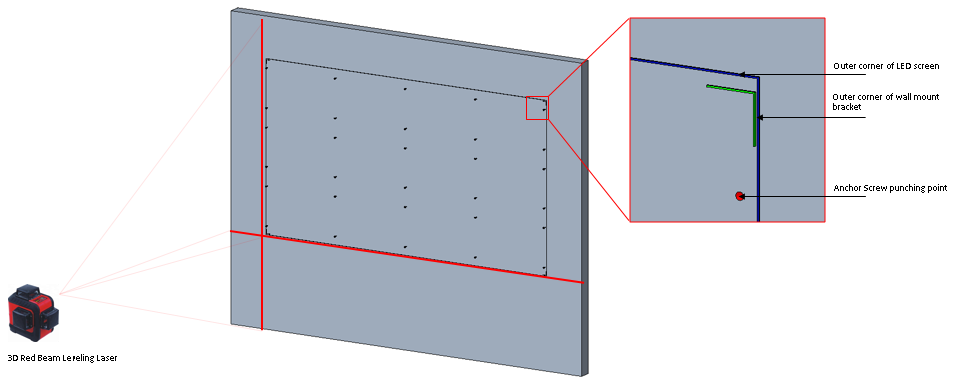
Therefore, make sure there are no obstacles in the LED screen installation area.
Examples of obstacles are Cable Cover Strip, Cable PVC Trunking, Power Cable Organizer Box, Wall outlet, etc.
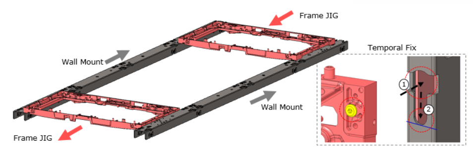
3. Assembling Frame JIG on the wall mount
On the plain floor, assemble Frame JIG on the 2 wall mount. Easy hooking system provides a quick assembling.
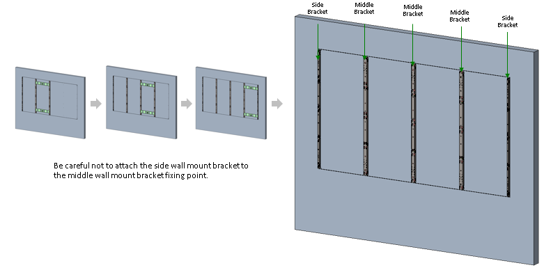
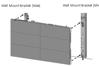
4. Fixing Wall Mount Bracket on the wall
Install the remaining Side Wall Mount Bracket and Middle Wall Mount Bracket on the wall using the Installation Guide Bracket in the same way.
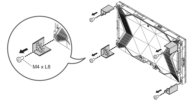
1. Removing Corner Guards
Corner Guard Block is attached to 4 places and is removed with a screwdriver.
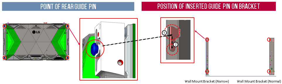
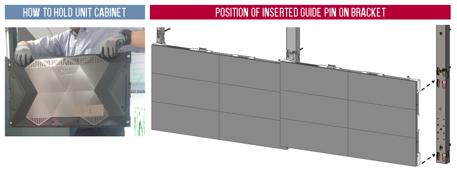
2. Attaching Unit Case
When the main unit cabinet is mounted on the wall mount bracket, the four rear guide pins on the back of the main unit cabinet are inserted into the guide hole ① of the wall mount bracket as shown in the figure on the right below, and pushed down slightly to fix it in position ②..
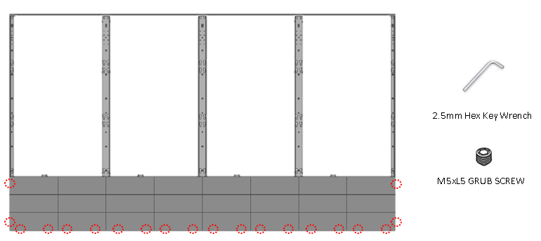
3. Adjusting XYZ
The very small gap between the main unit cabinets can be adjusted after all unit cabinets are installed. There are fine adjustment screws at 4 points on the top/bottom of the unit cabinet and 2 points on the left/right. Tighten or loosen these screws to adjust the gap between the unit cabinet LDMs.
Connecting Cables to the master
1. Structure of Cable port
Connect the power and LAN cable of the main unit case.
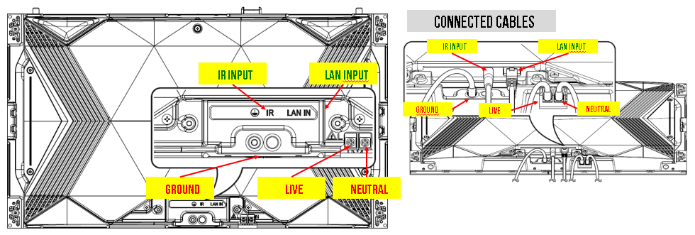
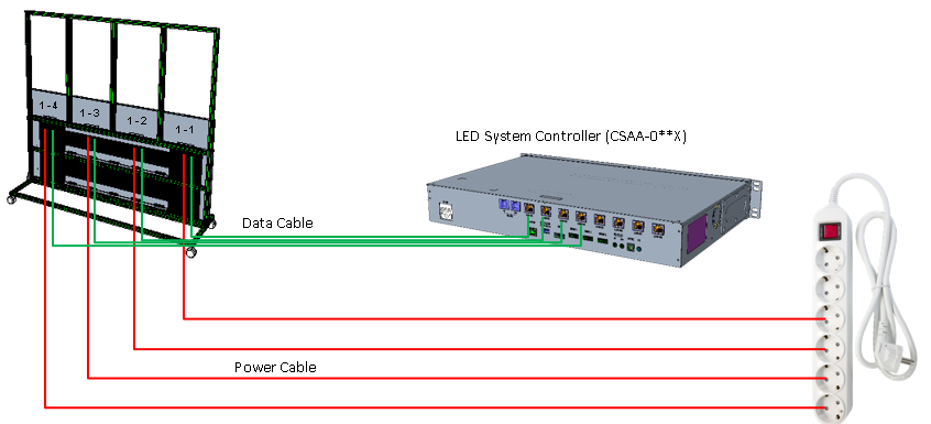
2. Connecting Cables
After the installation of the Main Unit Cabinet, connect the data cable and power cable as shown in the figure below based on the LED Screen diagram(FHD size).
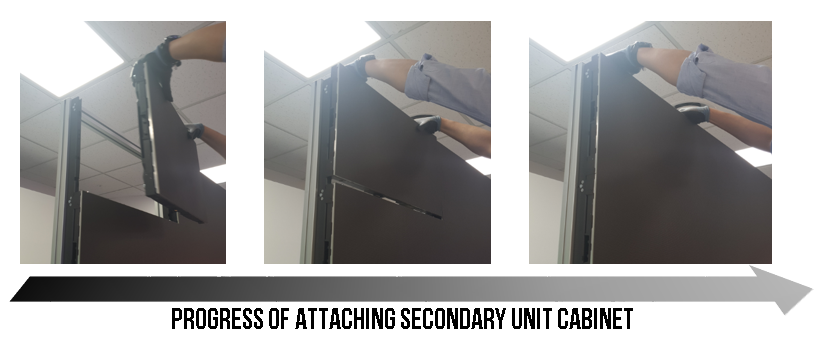
Attaching Secondary Unit Case
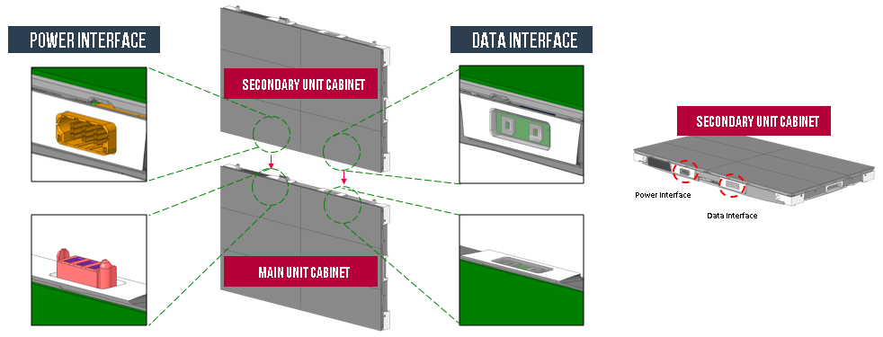
1. Structure of Connection between 2 unit cases
Mount the Main Unit Cabinet on the Wall Mount Bracket, and then fix the Secondary Unit Cabinet on the Main Unit Cabinet. At this time, the power and data of the main unit cabinet and secondary unit cabinet are automatically connected.
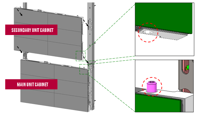
2. Attaching Secondary Unit case to Wall Mount Bracket
When installing the secondary unit cabinet, fix it by aligning the top guide pin of the main unit cabinet with the bottom hole of the secondary unit cabinet.
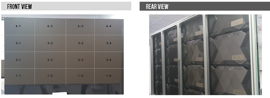
3. Front and Rear View of completion
The photos of the installation of the Main Unit Cabinet and Second Unit Cabinet are shown below.